The 310 mm F/1.9 Schmidt camera - finally nearing completion
by Dominic-Luc Webb
1. Introduction
The main objective here was the pursuit of a new optics adventure. I also had in the back of my mind photographic and high speed (>100 Khz) photometric (UBVRI and spectrographic) imaging of fireballs, comets, meteor showers, aurora borealis and other wide field objects that often have rapid transient features. The UBVRI color difference system is defined by Johnson (ref. 1 and references therein). The effective wavelengths of the UBVRI system are 360, 440, 550, 700 and 880 nm, respectively. While UBVRI was intended primarily for stellar objects, I use this for now, not yet having constructed a proper spectrograph. There is also a 13 color Johnson filter series (ref. 2) and I have been working on a filter changer for this. In addition to going for a challenging design, there were some questions I wanted to address. For instance, I wondered if it was practical to build a precision instrument from nothing but common industrial plate glass rather than optical glass. I also wanted to see if bee's wax could serve as a suitable replacement for conifer pitch. You could use any glycolipid, but bee's wax is cheaper and more widely available everywhere on the planet and smells better than pitch. I suspect it is also much less dangerous to inhale. If this works, I'll take up beekeeping next Spring (wanted for other things anyway).
I wanted a very fast system, like F/1.9, to capture in excess of 7 degrees of sky, and the opportunity arose to experiment with slumped plate glass. Being a photographic (i.e., non- visual) system, there was also the challenge of making and using a convex image surface (field at focus is curved). Of course, such a system could also be amenable to large format cinematography (i.e., 70 mm and IMAX) and I am looking into these options. I have a design strategy to incorporate large format movie reels despite the convex surface (maybe this is how IMAX came to be?). Without any projection optics, the focused image surface is 36 mm diameter; providing a nice match for 35 mm film. The primary mirror is spherical 310 mm diameter F/1.55 slumped 19mm plate glass (slumping compliments Richard Schwartz, Hawthorne, California). I'll post the heating/slumping/annealing protocol later. The corrector is 250 mm diameter "Optiwhite" (ref. 3; low iron plate glass with reduced green color) with a 6 mm axial thickness. I consider Optiwhite to be common industrial glass since it can be ordered from virtually any window or artwork framing shop with a price comparable to common plate glass. Because the corrector has a somewhat smaller aperture than the primary mirror and bends light outward, this configuration always has a larger system focal ratio than that of the primary. As a result, the complete optical system has a focal ratio of F/1.9. The corrector diameter is 80.6% of the primary diameter, higher than standard 70% designs. This design offers 33% more light gathering. Further, the corrector is complemented by a lensless configuration with a small aperture stop, see below.
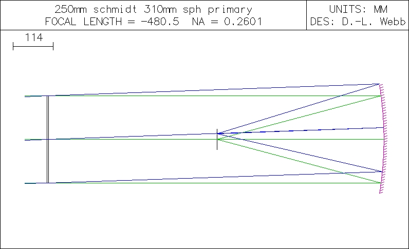
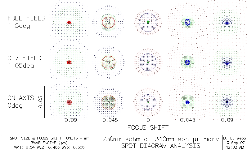
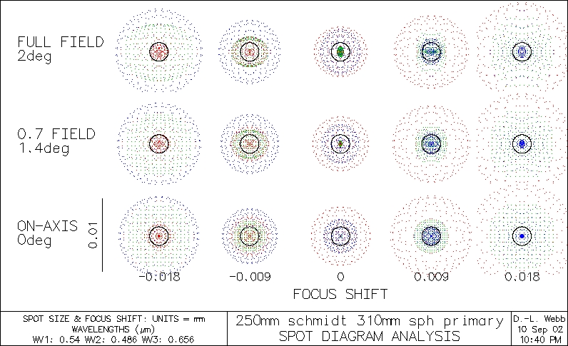
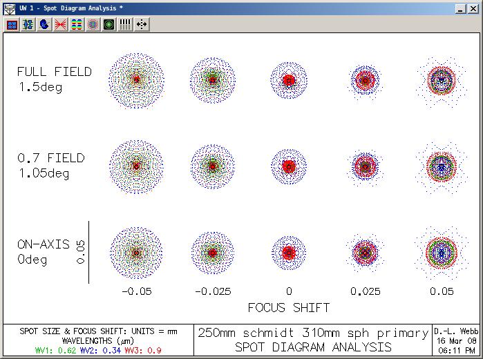
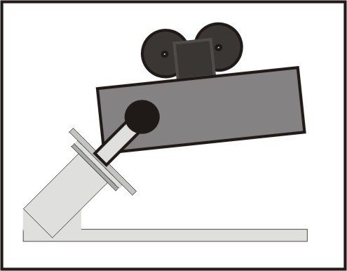
The first pic above shows the optical configuration. The second two pics are tricolor OsloLT (ref. 3, 4) simulated spot diagrams for the "standard" 86.6% and an "improved" 50% neutral zone (respectively) I originally selected for the present instrument - a "rich field" Schmidt camera. I found a bug in my simulation software (ref. 5 for debugged version), and when this was fixed, I got the spot diagram shown in the last pic to the right which uses the classical 86.6% neutral zone. Spots are now well under 50 microns from 340 to 900 nm (i.e., full UBVRI spectrum). This is a larger spectral range than usually shown in spot diagrams, so spots will be a bit larger. I came to an interesting observation. The bug in my software was calculating the curve using corrector diameter instead of radius, so the result was just a smooth, roughly hyperbolic curve without the steep depression around the neutral zone near the edge. It looks like one can just as well use a rather simple convex curve and still easily get within a 25 micron photographic criterion across most or all of the field and spectrum. I found an optics textbook in the Berkeley (California) City Library (ref. 7) that mentioned that a Schmidt corrector need not be terribly precise in terms of the exact shape of the curve. As a result, molding from metal or plastic forms is sufficient, even for some precision medical instruments. While this is design criteria dependent, there seems to be some truth to this general statement. This fact is exploited in the construction of the present corrector, and a simple manufacturing process for generating and polishing a higher order corrector surface is presented.
The image surface is convex glass ground to one half ROC of primary. In the present configuration, with the curve obtained after fixing the bug, the system approaches the diffraction limit for most UBVRI wavelengths (again, last pic above) at optimal polychromatic focus. I once estimated that if built within specifications, this system will capture in excess of 6 degrees of field of up to 14-15th magnitude stars in 60-120 second exposures on 3200 B&W film! This system is a prototype for two considerably larger cameras, a 500 mm single-mirror camera and a multi-mirror array camera of 1.2 meter mirrors. I now have the glass, but am still testing some different prototypes prior to any grinding. There is also some experimenting going on regarding sag of large aperture correctors.
2. Design and equations
Much of the design learning can be had from one book, called "Telescope Optics" (ref. 8). I recommend reading this.
2.1 Atmospheric scintillation considerations
One further matter I wanted to resolve was building a system fast enough to outpace atmospheric scintillation (i.e., moving shadows). Scintillation is caused by particulate matter in the upper atmosphere moving around and causing stellar photons to stray from their direct route to the ground due to reflection and refraction as well as absorbance. This is particularly problematic for high speed photometry, like measurement of stellar scintillation. There is a rather thorough set of 3 recent publications on this topic with relevance to telescope design and high speed photometry that offers some glimmer of hope in subtracting atmospheric effects from stellar scintillation (ref. 9-11a). I would really like to get some info on S values (scintillation factor) for Sweden if anyone has them. Approximations would be OK. I would like to know what is mean, minimum and maximum S, nightly and seasonal fluctuation as well as particle size, velocity, absorbance and refractive properties. I would imagine the intensity is wavelength specific. I have this idea of high speed imaging that is capable of defeating the effects of atmospheric scintillation. With enough info, I might be able to configure the present system specifically to accomplish this. It is widely accepted dogma that there is an optimal magnification and aperature combination for a given level of atmospheric scintillation, for instance. The present instrument is the fastest thing I have ever built that will have any magnification to speak of (the 0.5 meter scope and the 1.2 meter array should both exceed this someday). I could envisage changing the design or even using adaptive optics to compensate for atmospheric turbulence. Come to think of it, is this turbulence, or perhaps, sometimes really atmospheric laminar flow? I wonder if there is a Reynold's number for this. It would also be nice to get a hint how high elevation I would need to escape most of this. I am concerned that Mount Everest isn't high enough. Lacking a space-bound option, mere mortals such as myself will need creative sampling techniques. For now, it looks like some sampling will be done at 100 Hz, after discussions with Terry Galloway over in Berkeley.
2.2 Lensless Schmidt configuration
Above are spot diagrams for 250 and 125 mm aperture stops, 100% and 50% of full aperture, respectively, for a system with the corrector omitted. No originality here! Bernhard Schmidt is quoted as having stated back in the 1930's that a functional camera (he never called it a Schmidt camera himself) could be built without obligatory requirement for the corrector plate if a sufficiently high focal ratio is used (by means of an aperture stop). Since starting this project, I have found a published example of such a telescope which has been used with great success (ref. 12). I have yet to see Schmidt's comment in print. The only paper I possess written by Schmidt does not mention this (ref. 13), but I'll hold Schmidt to his (alleged) word. I am going to test this lensless configuration first, since the corrector doesn't need to be completed to do so. The primary is in the final polishing stages. At this focal ratio, I don't even need an aluminized surface to do such a test. The advantage this configuration offers over a Newtonian rests in the very wide field. The Newt suffers from coma, which is a lateral aberration, increasing exponentially with increased field. Without a corrector, the Schmidt design suffers from spherical aberration; an axial phenomenon that can be adjusted simply by selecting an aperture stop that meets performance criteria for a particular application. I estimate the present system will satisfy a 25 micron photographic criteria up to several degress of field without the corrector with an aperture stop radius of about 75-100 mm, and possibly more. This should still easily handle 13th magnitude stars within 1-2 minutes on 3200 film. Quite acceptable!
2.3 Corrector design - classic Schmidt
One needs to first solve for the deviations in thickness as a function of radius for the corrector (the "Schmidt" curve). The present design places the (relatively) flat side facing the stars, and the Schmidt curve facing the primary mirror. The Schmidt curve presented here is calculated using the measured refractive index for Optiwhite glass in green light (540 nm, n = 1.5211, see ref. 14). The refractive index for this glass is much in line with that of common soda plate glass (ref. 15,16). It can be seen from the simulations that the spot sizes for different wavelengths are not exactly linear as function of wavelength. In other words, one would not simply decide on what range of wavelengths are desired and choose the refractive index of the median wavelength to calculate the curve. My simulations indicate that spots increase in size exponentially with increasing wavelength. Thus, if one wishes to have spots of similar small size, it might be optimal to use a refractive index for a higher wavelength (i.e., more red) than the median wavelength for these calculations. I'll plot spot size as a function of wavelength and refractive index sometime, once I get the Siedel coefficients for this working as I want. Two questions I have been asked, that I do not yet have an answer to is how homogeneous is optiwhite and is there wedge and how much do these parameters affect performance. The homogeneity issue likely depends on the source and specific production run. The wedge effect could be calculated. There is slight variance in the thickness of this glass, on the order of a couple tens of microns, at most. I do not know how to make this calculation with Oslo and have not had time to manually calculate this. I have no idea if optical glass would be any better in this regard. My 11.5" Mak corrector plate (fine annealed BK-7) came to me with considerable wedge.
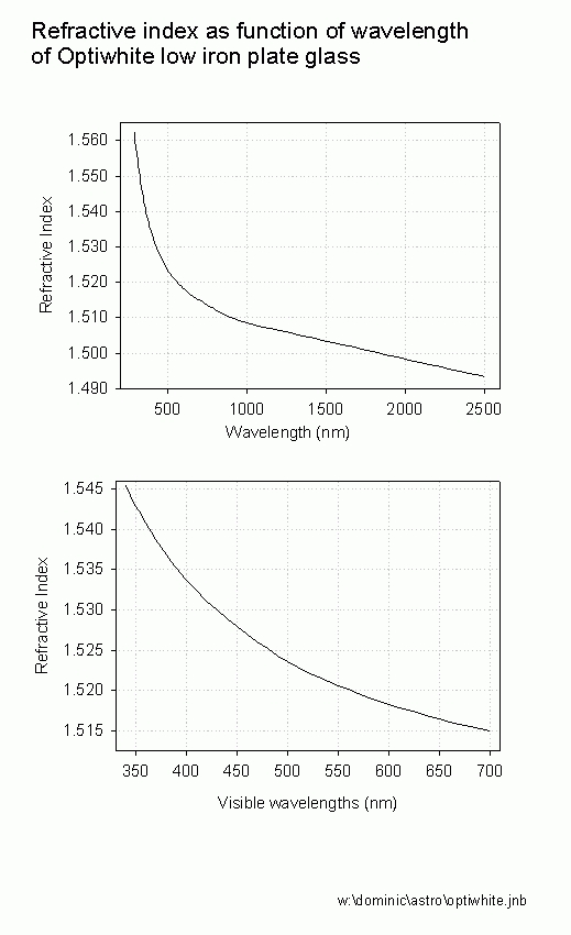
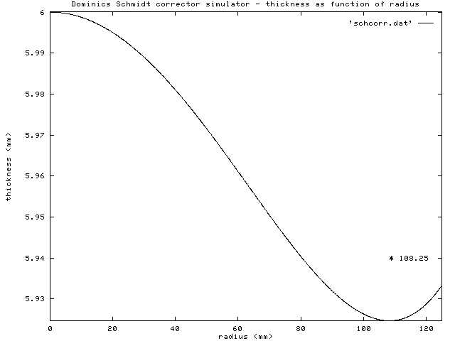
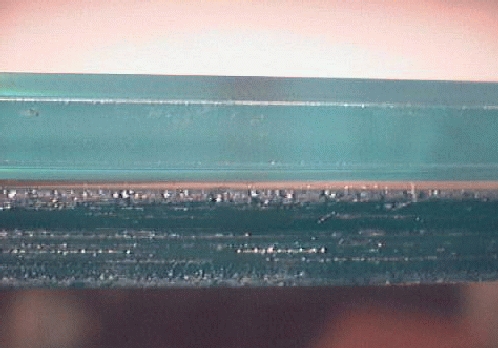
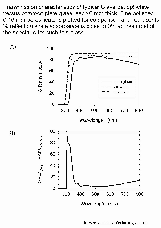
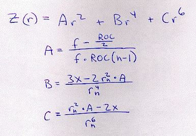
The first pic above, taken through a 40 cm length of the "optiwhite" corrector glass sitting on top of common plate glass of similar length, demonstrates the reduced green color due to low iron content. The second pic shows the transmission curve from 200 to 800 nm (accurate to 3rd decimal) by spectrophotometry compared to plate glass of same thickness and a very thin (0.4 mm) piece of fine polished borosilicate (microscope cover slip). This indicates that about 20% of axial light (visible) is reflected, since we do not expect much absorbance from such a thin piece of glass. The third pic is a plot of refractive index as a function of wavelength obtained by TIR refractometer from data in ref. 14 (accurate to 5th decimal). The last picture is the result of my effort at simulating the optimal Schmidt curve for this system; some C source code to solve for the 2nd, 4th and 6th polynomial terms and then write data to file along with a configuration file for Gnuplot (ref. 16b) to plot the result to PS and PBM formats. See reference 6 for my source code. The code can be edited directly for any specific design, details at the top of the file. There are a few equations around, which may or may not be polynomial. For my F/1.1, I solved a non-polynomial equation system for variation in thickness and ran some Matlab code to fit the data points to a polynomial function. The reason to do this is partly for the purpose of entering the shape of the corrector into simulation software (which usually expects polynomial coefficients, as I have learned). The first three (even exponents) polynomial coefficients are probably sufficient for most Schmidts, but I suspect that for very fast systems, perhaps the present instrument, even more terms may be needed for optimal performance. Note that for the F/1.1 I used a 9th order polynomial fit. In a nutshell, we need to solve the following higher order polynomial, which ignores terms for the odd-numbered exponents:
z[r] = Ar^2 + Br^4 + Cr^6 (Eq. 2.3.1)
where z[r], the deviation in thickness relative the axial thickness, z[0], is a function of r, the radius. If one adds the axial thickness to this equation, the following equation describing the thickness, T, at any point along the radius is obtained:
T[r] = z[0] + Ar^2 + Br^4 + Cr^6 (Eq. 2.3.2)
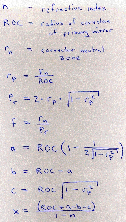
The A, B and C coefficients are each somewhat complicated equations. I'll get to these after a few more lines. As I will demonstrate, solution of this equation is useful not only so you can see what is possible when the coefficients are entered into simulation software. It can been used to determine a deformation to be used for polishing by slightly warping the corrector. After releasing the lens, it magically springs into the correct shape. Keep in mind computers with parallel ports and precision stepper motors and drivers were not available to Schmidt. Rather early on I reasoned that solving for z(r) could be used to solve an equation that could be written into software to control a stepper motor driven grinding/polishing machine to generate a very close approximation of the intended curve by use of this equation:
t[r] = 2 * pi * r * (z[0] - z[r]). (Eq. 2.3.3)
That is, the relative amount of grinding/polishing time, t, at a given r, is just the difference in thickness relative that on axis, z[0], times the perimeter for that particular distance from the axis. It should be a piece of cake to drive a stepper motor via the parallel port, for instance, to generate the curve, regardless of how complex the optimal design curve ends up. That is, the computer could in principle be programmed to control the motions of a motor consistent with a 9th order curve if that is what one wishes to obtain. I am tired of typing, so here comes the scribble scrabble. This is the exact solution to the Schmidt curve to the 6th exponent. If you're in the mood for a major headache, feel free to try and derive this (see ref. 8):
3. Cutting, grinding and polishing
3.1 Primary mirror
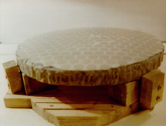
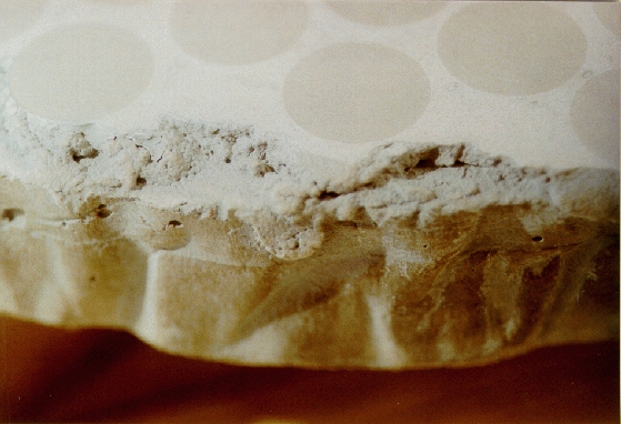
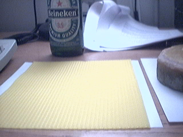
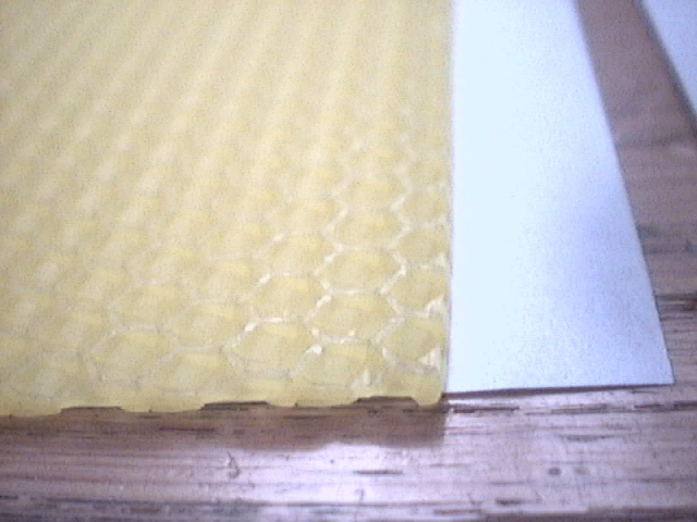
The above pics are: 1) the jig showing how the tool is suspended, 2) concrete grinding tool with tiles mounted over surface, 3) closeup indicating just how crude the edges can be and still result in a flawless mirror, 4) bee's wax "sheets" as I purchase them. These are US 8.5x11" and not European A4 which the wax is laying on in the pic (cue to giggle), 5) closeup showing the hex patterns that bees use as foundation to build a new hive, 6) concrete polishing tool with a roughly 5 mm layer of bee's wax and 7) primary mirror sitting on the polishing tool (note how very slumped this beast actually is. Just imagine getting this down to 20th wave rms!!!).
I made a couple observations about bee's wax. As near as I can tell, the bee's wax works out to be about 3 times cheaper than Gugolz pitch. It is also a lot easier to get ahold of. While the Gugolz folks down in Switzerland would quite possibly commit suicide before they'd sell you a single canister of their precious conifer pitch, Swedish bee farmers have thus far seemed very pleased to find a new outlet for the fruits of their bee's labor. In terms of handling, wax versus pitch is a tossup. I was able to slowly warm up the wax inside the house on the stove without much fumes. What smell is given off is not very offensive, and some folks might even find it pleasant. If it is boiled, which is unnecessary, the fumes will require that heating be done outdoors. Pitch simply must be heated outdoors and the fumes never smell very good. Hot bee's wax pours like water. The rim for pouring onto the concrete needs to be watertight. If it leaks water, it will leak melted wax. The wax hardens rather quickly, so one needs to remove the rim quickly and start working the wax almost immediately after pouring. It was a tad difficult to get the curve into the tool due to the deep sagitta of the primary mirror. I ended up with a very simple solution. I litterally painted the melted wax onto the tool with a paint brush as needed to get a reasonably convex surface. I made this tool when I got to #400 grit. I ground the polishing tool with #400 grit. I next poured, then painted, more wax over the surface. I went on to #600 and #1000 SiC. In terms of polishing, bee's wax takes a little time to get used to because the fresh wax tend to peel as it is worked. I am presently in the polishing stages with the primary. I have discovered that furniture clamps are very handy for pressing mirror and tool together to get optimal contact. This works best with a little warming. However, if the wax actually gets close to the melting point, the two surfaces will fuse. The same furniture clamps can be used sideways to pry the two surfaces apart. In one case this was successful and I went on my way polishing. In another case, the tool was destroyed and there was a lot of wax caked onto the mirror. I scraped this away with a piece of wood, wiped it clean with nafta and poured a new tool. A couple hours later I was polishing again, no big deal. And this is the great advantage to bee's wax. It is so cheap that you start from the initial order buying a lot more than you actually need and have plenty extra for such mishaps.
I found pouring to lead to some problems. I now use a paint brush to paint a thin layer a couple mm thick on top of the grinding tool. This has many advantages. First it forces the wax to conform to the desired shape. Second, an inherent artefact, brush strokes, provides for channels.
3.2 Corrector
The concept I have developed and used here does not require any kind of vacuum deformation of the corrector. I have programmed a PC to drive a marble over the surface of the corrector by means of the parallel port and a stepper motor. Across a 400 mm section of the corrector, before I cut it to size, I estimated there was about 10-15 microns variance in thickness. I decided to start with #400 SiC, as this should be quite adequate to quickly remove this much error. The tool was an iron plate for the flat (shall we say flatter?) side. The depression at the neutral zone (86.6% radius in this case) is the deepest region of any Schmidt corrector. It is 75 microns deep in this design, a tad more than I want to risk with vacuum deformation. This is perhaps a good reason to test my stepper motor and marble technique (ref. 19 for my grinding software). Glaverbel, which manufactures Optiwhite, somehow sent my local distributor what we thought was the incorrect glass, having a faint turquoise color. I waited over 2 months for the local distributor to receive another shipment. The new shipment also had a faint turquoise color. The sample glass in the local glass shop originating from Glaverbel was completely clear. An interesting point emerged. There is no formal definition for optiwhite and this glass varies considerably between batches, so anything with reduced iron content can be called "optiwhite". While I am certain it really is within the technical means of Glaverbel to actually produce a colorless glass, I really did not feel like waiting yet another 2 months to find out. I went ahead and used the slightly colored glass.
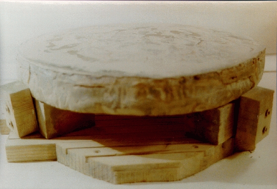
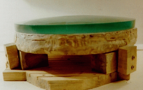
3.3 Image surface and film holder
The image surface is curved, with an ROC of 480.5 mm; one half that of the primary mirror. The entire focused beam has a cross-sectional diameter a bit more than 36 mm, so 35 mm film (measures about 35x24 mm) will capture most of the field. I recommend beer bottles to make this, but before you shop'n guzzle a six-pack, go for the largest bottoms you can find (I mean the beer bottle bottoms, right?)! Bishop's Fingers is quite large and tastes pretty good. Alternatively, Hobbgoblins or Fidler's Elbows are quite suitable in both respects. These all have decent curves already provided, compliments the bottle manufacturer. For the hard core drinkers, Black Death Tequila or Absolut Vodka bottles will more than work fine, remembering that drinking and working glass don't mix. To break out the bottoms, I wrap tape around the bottom and hit the side with a hammer. This is followed by a bit of grinding on a concrete tool. I recommend not polishing this surface. Leaving the surface slightly coarse, around 600 grit, is useful for focusing without exposing any film.
I am not holding the film in place with either adhesives or vacuum; see the picture above. Since I need a tool to grind the image surface, I decided I may as well use that as a clamp to press the film down. Both the image surface and the tool (now a clamp), are larger than than the image itself. The clamp has a 38 mm hole drilled through it to permit light to go through and hit the film that it presses from its edges onto the image surface. The two blue objects are spacers about same thickness as the film.
4. Optical tests
Several types of optical tests were used, or will be used, in the testing of the present instrument, including ronchi test, star tests, Couder masks, and sheering interferometry. I hope to someday write about the design details of each of these. What I can say for now is that my ronchi and interference gratings are home made, mainly with Polaroid Polagraph B&W slide film and the optical flat for the interferometer is a 1.25" Newtonian diagonal (BTW, a newton interferometer typically uses a full aperture flat, expensive!). Mine is cheap and highly effective, so that's what I use! The point is to measure the Strehl ratio, which gives an indication of quality of star images as a function of degrees of field for the specific optic that has been produced which has its own distinctive mapping of wavefront deformations (briefly described in ref. 17b).
4.1 Primary mirror
Before re-grinding showing more TDE than I will accept:
After re-grinding at 400 grit with very short strokes and working way to polishing with new painted tool TDE is gone, although replaced by a new central error:
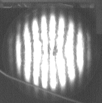
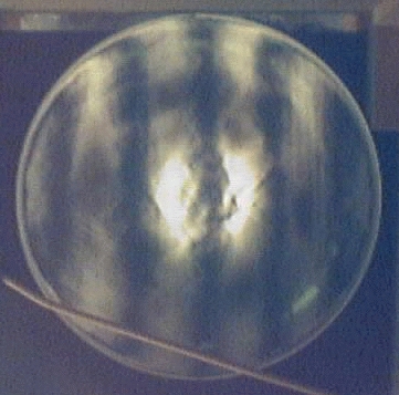
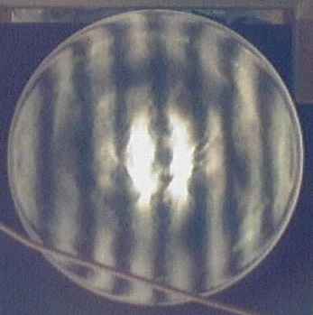
Above are ronchigrams I took very close to ROC manually holding my webcam up to the grating (100 LPI). The images were obtained by moving in stepwise increments away from the mirror at approximate distances from ROC of -10, -5, 0, +5 and +10 mm. The tester has two adjacent 35 mm frames with grating images. The light source goes through one frame, reflects from the mirror, and returns through the second frame about 2 cm beside the source. There is a hole in the plate that holds up the second grating for the camera to take a picture (or for an eyeball). This tester uses a 50 Watt Halogen bulb, which I reason is not overkill because I use etched glass plates and filters to condition the beam. I got the lines suggested by these ronchigrams after about 45 minutes of polishing on bee's wax using MicroAbrasive 2 micron Microgrit CeO. Basically, I got a sphere, but with unacceptably high amount of TDE (turned down edge). After some email exchanges with other ATMs indicating TDE was inevitable with such a short F/ratio, I decided to retrace my steps and experiment a little, believing I could do better than this, but perhaps not by polishing. I explored two observations: 1) TDE was caused by too much glass at the edge being removed relative the rest of the mirror, and 2) the wax was progressively being pushed out of, rather than into, proper shape.
I found a remedy for both of these problems. I cut out small triangular wedges on the edge of the tool such that the result looks like a gear. I did not want to use a subdiameter lap, reasoning that I still wanted continuous contact with the edge, but I wanted to reduce the amount of time spent polishing there; but only a little. This worked very well until I broke the polishing tool when I used too much (unnecesary) force to press the surfaces with furniture clamps. Since the lap consistently and progressively had a tendency to move around as I worked it, and it was now clear that the amount of TDE I had was not coming out with polishing before the Sun goes supernova, I decided to go back to 400 grit and work my way back to polishing using very short center-over-center strokes. When it was time to start polishing, rather than pouring onto another concrete tool, I tried (literally) painting a thin layer of wax over the tool and polishing with this. The result was immediately and clearly superior. There was very even contact across the entire surface and the reflectivity was spreading smoothly from the middle out towards the edge. As seen in the first "after" image above, with tester about 5 mm towards primary from focus, the TDE is entirely gone now, although the outer zone is not yet as reflective. Note that the high reflectivity region is a circle. There is a uniform error near the middle that thus far seems to be coming out. Note that in the "before" images there is ring shaped region of poor contact between tool and mirror, which proves the old polishing tool that was poured and much thicker, never really broken in. I have not made any effort to measure this exactly yet. The TDE experiment is done. I am now polishing more and making more precise measurements.
4.2 System with corrector
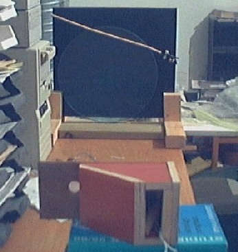
No optical test was done on the corrector alone although a spherometer was used to get the relative difference between axis and neutral zone prior to fine grinding and polishing. The first test employed here tests the ronchi interference pattern appearance of the entire optical system.
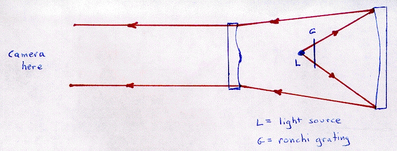


The first image above shows the system test setup. The key points to notice are that the light source is at prime focus on-axis and ronchi grating is directly in front of this. An image of the ronchi grating is projected onto the primary mirror and out of the system, through the corrector plate. From a number of ROCs away from the corrector, a camera is placed to take a picture of the ronchi pattern for evaluation of how the path of the photons had been affected by the corrector plate. Obvisouly, the primary mirror needs to be completely figured before this test can be meaningful. Through repeated cycles of polishing and measurements, corrections can be made.
5. Silvering, aluminizing and other coatings
Consider this: fine-polished glass still reflects about, let's say, 10% of the light that strikes its surface. Actually, I suspect more, but let us say 10%. The following equation can be used to get the diameter for a mirror with twice as much area, and hence fully compensates for photons lost to transmission:
Du = 2 * [(Dc/2)^2 * Rc/Ru]^0.5 (Eq. 5.1)
where Du and Dc are diameters of uncoated and coated mirrors, and Ru and Rc are reflectivity of uncoated and coated surfaces, respectively. It is noteworthy that in some cases, Ru/Rc is small, and as a consequence, as little 20% more diameter could give same light gethering capacity without need of a reflective coating. Given the log nature of magnitudes, and the fact that aluminizing can be the most expensive component of the optical construction, especially as aperture increases, dispensing with it might be more than just an acceptable alternative. The present mirror has about 3500 times more area to collect light with than the human eye, so the bare polished surface without any coating still collects about 350 times more light (90% is lost) than the human eye. That's a decent number of magnitudes. It should also be mentioned that even high quality aluminized and silvered surfaces have residual transmission. There is a further rationale for not silvering or aluminizing. These practices deposit thin films of metal over the precision polished surface. These have varying degrees of precision in thickness across the surface, meaning there is an inherent departure from the polished figure as a result of any coating. So what of light reflecting back from the back side? I am trying just coarse grinding and black paint. Time will tell how well this works. My first star tests seem encouraging. If I coat, I will likely go with silver.
6. Film and photography
Stars per pixel or pixels per star? In the present case, it could be stars per pixel. Consider this: Ray tracing indicates that about 100% of photons from an infinitely distant point source (a star is pretty infinite) land in an area only 5 microns in diameter. This is so for all visible light across the entire optical field at full 250mm aperture. The film I have chosen is 35 mm Ilford Delta 3200 B&W print film (ref. 11b), or the 120 version with a projection lens. The rating of this film indicates it should be about 8 times faster than conventional Tri-x 400 B&W film. Don't let the high speed deceive you. The grain size of this particular film is 10 microns, somewhat smaller than conventional films used for astrophotography. The spectral response of this film remains at a plateau of about 80% or more of peak response from 380 to 680 nm, covering most of the UBVRI. It really is upsetting that Ilford doesn't make something like this in movie reels. I'd sure as heck buy it! Alternatively, Ilford does make 35 mm film reels of a 400 series.
Perhaps a word is due here regarding CCD imaging. Consider that this camera has a very large image surface. If one is to capture the entire image surface, one would need a 2" square CCD. I think the Kodak photometric KAF1400 2x2" chips are about 70 000 USD (about 1 million SEK with tax). In addition, to implement this, one would need a very specialized field flattener that would have to be custom built. It would be a major innovation for Kodak or Texas Instruments to come out with convex CCDs. Remember, CCD detectors are silica based, and perhaps they could be ground and polished to some geometry other than flat. I won't hold my breath. I'll use a B&W webcam and grab only a small part of the optical field on those rare occasions when I must use a CCD. I am presently working on another solution.
7. Thermal stability
Everyone asks me about this and I am not sure what to make of thermal stability in the present case. On the one hand, plate glass is not precision annealed, so it is not terribly homogeneous, suggesting instability. On the other hand, this glass is very thin, meaning it should equilibrate more quickly. Being so thin, it is lightweight, so motion control should be far easier than with a traditional 1:6 thickness. I am banking on thin plate glass equilibrating with ambiant temperature so much better that it will exceed 1:6 thicknes borosillicate. Amateur astronomers, as opposed to pros, tend to move their scopes from warm homes to the freezing outdoors, so there is a serious temperature differential. However, thermal expansion is extremely low for any glass; industrial or optical grade. I am more concerned about precision motion control, particularly tracking, which is easier in the present case, simply less weight for the stepper motor to push if the mounting is not perfectly gravity centered. I'll try and think of some cute tests in this regard.
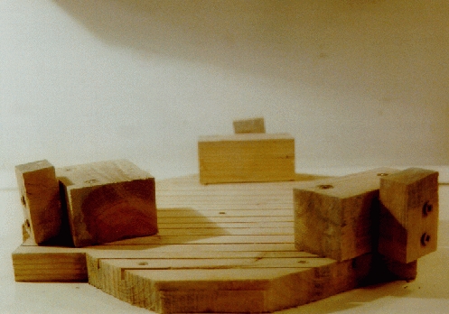
8. Mounting and motion control system
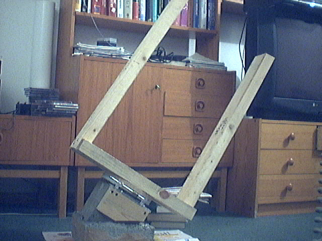
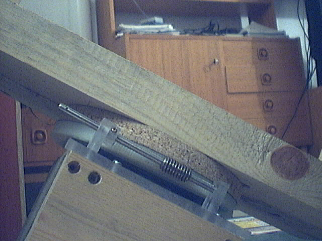
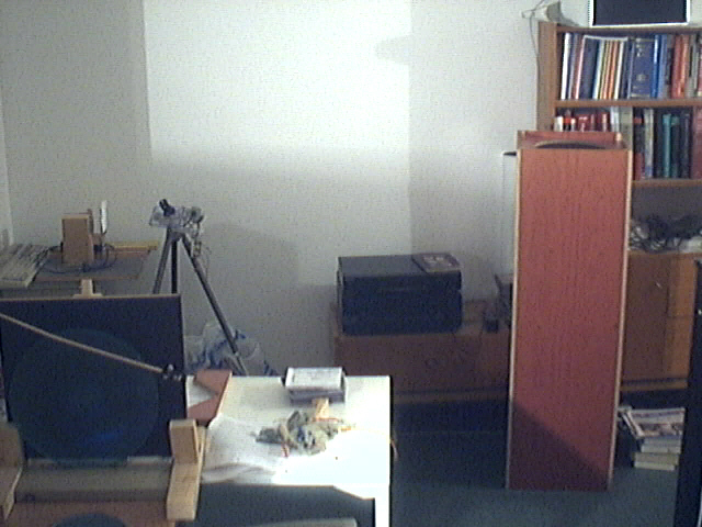

For the mount, I poured a concrete block with the base tilted approximately 30 degrees consistent with my local latitude of nearly 60 degrees north. This seems like an excellent solution for my location since the block serves as my polar axis and points nearly vertically. A wooden fork mount is bolted through a spacer (for a worm), a worm gear and chair bearing into the concrete mount. I still have some stabilizing to do before I feel this is rock steady. The second pic above shows a closeup of the clock drive worm and gear purchased from Andy Saulietis of the ATM list. Third pic above shows the plywood tube on the right and the primary mirror in its holder for the optical tester on the left. Note that the tube is considerably shorter than the book shelves in the background; one of the great advantages of a low focal ratio. In the background to the left is a camera tripod with one of my homemade stand-alone stepper motor based clock drives. The Schmidt camera also need not be driven by a computer, as I am building another stand alone stepper motor driver that is tuned from a timer IC and drives the motors via a Johnson counter and a Darlington array. Mainly, I plan to use the computer, actually, but this is sometimes faster and easier, not requiring a computer.
For computerization of motion, I will use my usual STP software setup. Basically: the stepper motors from the stand alone circuit interface with, and get pulse information from, the parallel port of a PC running any flavor of UNIX. I wanted to run the drive from a Sun, but this turned out to be a real headache. Sun does not offer much info on how to program via the parallel port of a Sparc Station other than you cannot get direct access as with Linux on a PC by directly opening a port and writing bits to it after ioperm. One has to go through Sun's proprietary drivers BPPIOC_SETOUTPINS and/or BPPIOC_SETPARMS ioctl for which they offer no example code. If anyone knows how to write such code, I would really appreciate an example. I am looking into replacing the SunOS with Linux to get direct access, and some other reasons. My STP software, which presently runs on a PC, drives the motors using coordinates from Xephem ephemeris software. Importantly, STP was designed to run autonomously over a radio network and is happy working side-by-side with AX.25 ham radio (data mode) using TCP/IP protocol. In essence, the scope can be on a mountain top, or some other cold place, like Marsta, Sweden, or even Mars, and the user can be sunbathing on Santa Monica beach sitting behind a computer choosing what part of the sky to image. Obviously, this is not compatible with photographic imaging. Just wait till you see the digital imaging system I worked out for this! I still do not have an FTP site for my software, but I am slowly submitting it to Image Reduction and Analysis Facility (IRAF, ref. 12). The main packages are STP, PMTI and PRISM.
9. Real application: photographic tests and evaluation
9.1 Lensless configuration
9.1.1. Rainbow and other wierd optical effects
I have gotten rainbow. It really is not hard to get with such a mirror. When properly aligned, a collimated Schmidt camera behaves as it should, with all wavelengths converging at the same point. However, when misaligned, the mirror begins to act more and more like a prism, placing different wavelengths at different off-axis coordinates. My first experience with this was when I made my first Schmidt and immediately after 15 minutes of polishing, when the mirror surface was looking just barely reflective when dry, I rushed out to take a look at a reflection of the Moon. I just propped the mirror up and stuck my eye into the optical path. Obviously, there would be substantial instability in this case and a lot of tilt. What was seen was a grey Moon with a blue semi-disk on one side and a red semi-disk on the other side running along the radius. It is an interesting effect to look at, seeing the Moon in a couple of different segregated colors. Once the fun is over, careful alignment eliminates this problem.
9.1.2 Photographs in lensless configuration


The pics above indicates the remarkable quality of this camera system without any corrector plate whatsoever. The first pic is Orion, and I believe the Orion officienados will agree these came out spectacular!
Current dogma states that the Newtonian telescope is the "simplest telescope to construct" and this is what virtually every newby first attempts. Given that the lensless Schmidt has only one optical surface, and this is spherical (the easiest of all optical surfaces to produce and test), this design is much simpler than a Newtonian. Much could be said about the natural baffling of this system as well, given that the tube is at least as long as the ROC of the primary. A typical newt tube would only extend perhaps 10-20% beyond the focal point.
9.2 System with corrector


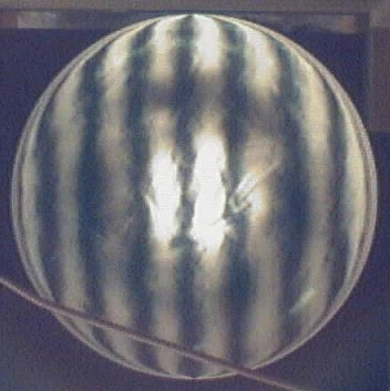
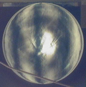
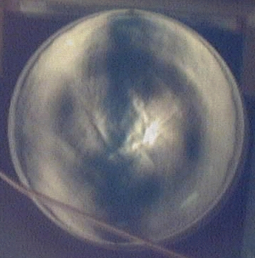
Above is a series of pictures taken with the corrector. Compare these to the ones above in the lensless configuration
9.3 System evaluation
10. Concluding remarks
Thus far, I find no reason not to use plate glass for either a primary mirror, even in this extreme case, or for a corrector, albiet, colorless low iron glass should be used. Bee's wax has provem acceptable as a polishing substrate with the proviso that it takes some getting used to. There are a number of other interesting substrates that I have considered, such as shellac and polyurethane.
11. References and Links (I don't have all as PDFs, so use ref. 28 for those articles):
- 1. Johnson, H.L. Interstellar extinction in the galaxy. Ap. J. 923-42. 1965
- 2. Paper on 13 color Johnson series
- 3. Glaverbel - Belgian manufacturer of Optiwhite
- 4. OsloLT Optical design software
- 5. Len file from Oslo-edu (Linux Slackware kernel 2.6.19, KDE3.5), last checked 16 Mar 2008
- 6. C source code for determining all 3 polynomial coefficients for Schmidt curve + gnuplot output
- 7. General Optics, Berkeley.
- 8. Telescope Optics: Design and Evaluation. Willman Bell Publishers
- 9. Dravins, D., Lindegren, L., Mezey, E., Young, A.T. Atmospheric intensity scintillation of stars. I. Statistical distributions and temporal properties. PASP. 173-207. 1997.
- 10. Dravins, D., Lindegren, L., Mezey, E., Young, A.T. Atmospheric intensity scintillation of stars. II. Dependence on optical wavelength. PASP. (109)725-737. 1997.
- 11. Dravins, D., Lindegren, L., Mezey, E., Young, A.T. Atmospheric intensity scintillation of stars. III. Effects for different telescope apertures. PASP. (110)610-633. 1998.
- 11a. Dravins, D., Lindegren, L., Mezey, E., Young, A.T. Erratum. PASP. (110)610-633. 1998.
- 12. Fawdon, P., Gavin, M. A lensless Schmidt camera. J. Br. Astron. Assoc. 99(6):292-95. 1989
- 13. Schmidt, B. Zentral Zeitung fur optik und mechanik, 52 Jahrgang Heft 2; Mitt. d. Hamb. Sternw. in Bergedorf, 7, 15, 1931-32 (No. 36). English translation by Mayall. 1946.
- 14. Refractive index data for "Optiwhite" low iron plate glass
- 15. Anthony Stillman's table of plate glass refractive indexes
- 16. More info on plate glass refractive index
- 16b. GNU Project & Free Software Foundation
- 17. Polaroid website about Polagraph HC B&W slides and autodeveloper (need new link)
- 18. 100 LPI grating image (add image)
- 19. C source code to drive grinder
- 20. Ilford Films
- 21. IRAF - Image reduction and Analysis Facility
- 22. Biredskapsfabriken i Toreboda (Sweden). Tel:Int+46-0506-10273, Fax:Int+46-0506-10004
- 23. Dave Rowe on Schmidt math
- 24. ATM page info on making/testing Schmidt correctors
- 25. Short explanation of Strehl ratio
- 26. Willstrop, R.V. A simplified null test for a Schmidt camera aspheric corrector. Mon. Not. R. astr. Soc. 192. P455-66. 1980
- 28. NASA ADS Astronomy Archives, download above article here
Dominic-Luc Webb dlwebb@canit.se
http://www.canit.se/dlwebb/catadioptric/310schmidt/310schmidt.html