230 VAC 2300 Watt Non-Induction Load Dimmer Circuit
By Dominic-Luc Webb
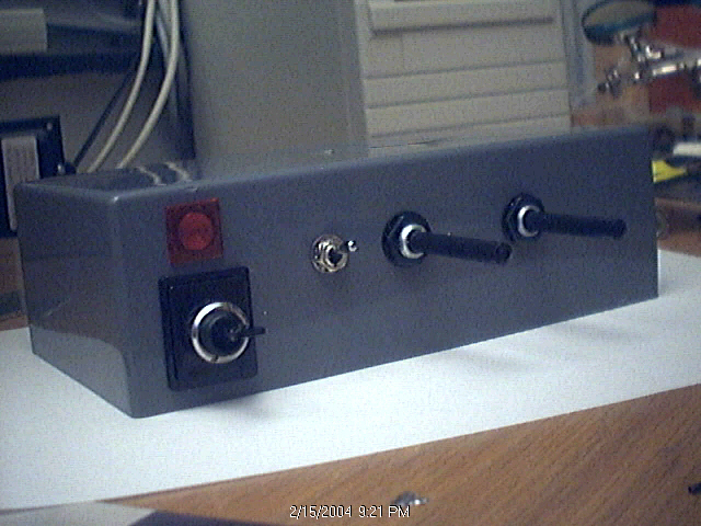
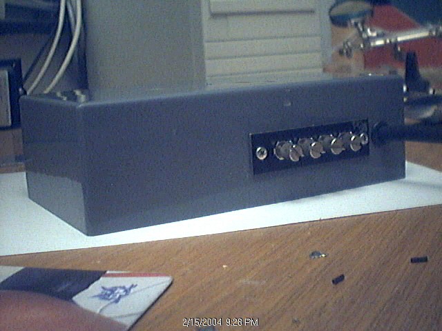
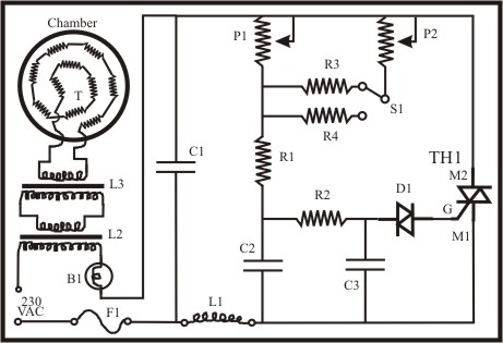
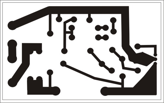
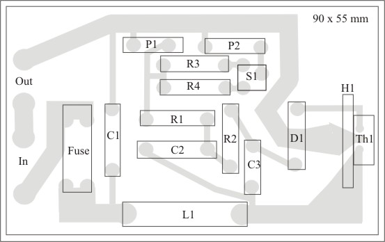
The top pics are front and rear of the project box. The present application is a control unit for melting and then vaporizing aluminum in a high vacuum in order to make optical mirrors. Production of filters is another goal. The 3 pics directly above show the schematic, a PCB layout and component placement for this 230 VAC 2300 Watt control; basically a precision high power version of a common light dimmer circuit. The schematic includes a light bulb (B1), a couple of transformers and 10 resistances (T) in series inside the vacuum chamber. These resistances are 1.0 mm diameter by 40 mm long green (99.7% Tungsten) TIG electrodes (Tungsten Inert Gas). Those components are not included in the PCB layout which only works as a light dimmer circuit and could in principle be connected to many other things. In order to get the smoothest operation from completely off (or prewarmed state) to the maximum allowable power, this circuit uses two potentiometers (P1 and P2). P2 sets the power range, while P1 sets the intensity as any normal light dimmer would behave. P2 (note also R3 and R4) permits the electrodes to be slightly prewarmed when power first comes on without actually melting the aluminum, while restricting the maximum power. That is, we want to prevent overshoot which could melt the aluminum too early or dissolve or sublime the tungsten (tungsten is somewhat soluble in molten aluminum). Then P1 can be turned to finely get to melting and then vaporizing. P2 can be any 280 degree pot, maybe even a board mounted variant, but I think it is nice if P1 can be a decent 360 degree or even 10 turn panel pot. I know this circuit to work well, but I plan to replace the wimpy transformers L2 and L3 with something more powerful.
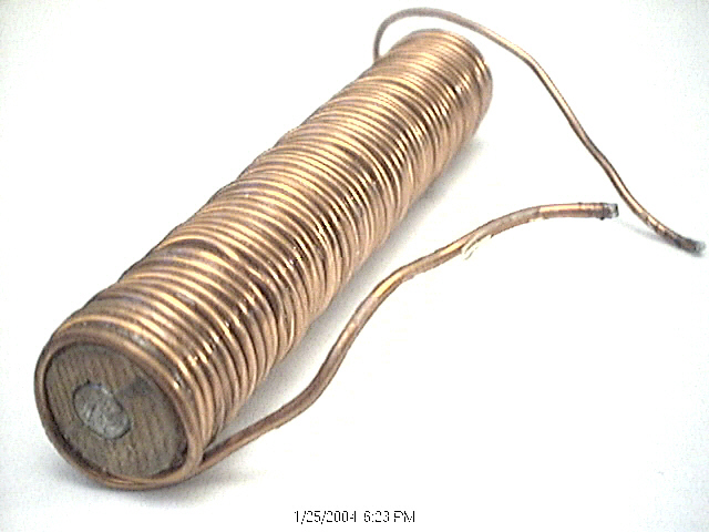
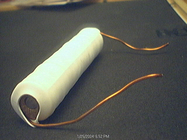
The two above pics show a choke that I made, not finding a suitable one in the local shops. I took a 15 mm diameter wooden dowel and drilled a 6 mm hole through its length and drove a 6 mm steel rod through the middle, checking first with a magnetic screwdriver to see that it was ferro-magnetic. I then wrapped 58 turns of 1.4 mm transformer wire around the dowel and sealed the whole thing up in heat shrink using a heat gun. I do not know what the current capacity is for this choke other than bunching up the wires brings down the capacity, but it does not get warm to the touch even when I power up the electrodes to the point when the 6.3 amp fuse blows. I think it is safe to say this choke will easily carry more than 6 amps. It makes no sound at any level of dimming and I have not detected any RFI. The aluminum heat sink is not optional. Skipping it could kill the triac. The point of bulb B1 is to protect the transformers from overheating, although I found that if placed in series it will better prevent them from humming associated with transformer core hysteresis. The point of this exercise is to heat the electrodes T sufficiently to melt and then vaporize reduced aluminum sitting on them in a vacuum chamber at 10e-4 Torr or lower pressure. I estimate that if the electrodes reach the point where they are visibly red hot, they are well above the required temperature for this job. Such waste will needlessly overwork the whole circuit. I think it would also cause a great deal of unnecessary wear on the electrodes. The point in having the electrodes in series is to stop the entire aluminization process should any one electrode fail, preventing uneven deposition of the aluminum on the optical surface.
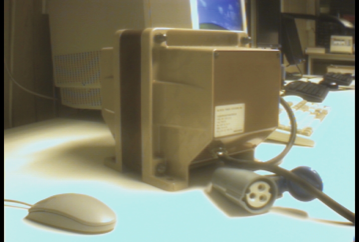
Not yet added to the schematic, but on the PCB and component placement figure are 2 parallel resistors (R3 and R4) above R1 that feed through a single-pole 2 way switch to P2, allowing fine tuning of the range. R3 and R4 can readily be changed for some other values if they do not allow appropriate tuning. The third pin on the potentiometers are wired directly to the appropriate pin on the pot and is never wired to the board. One could experiments with addition of some resistors here as well. I finally found a decent transformer. It is a 230 VAC to 230 VAC 2000 Watt transformer. Several got discarded at my work and I decided to try and put one to (good?) use. I will try to take it apart and unwind one side to get a decent step-down. Both sides have 3G 2.5 mm^2 wiring! Check this monster out (it is sitting just in front of a 25" monitor)....
Parts:
Fuse 230 VAC @ 10 Amp (must be F-type)
C1, C2 150 nF @ 400 VAC (X-class)
C3 33 nF @ 400 VAC
L1 40-100 uH @ 10 Amp (or higher amps, I used a 10 uH @ 16 Amp)
D1 ER900 or BR100-3 diac or equivalent
TH1 BTA140B-600 Triac, 600 VAC @ 25 Amp
P1 500 Kohm linear pot
P2 1 Mohm linear pot
R1 2.2 Kohm 1/2 Watt
R2 6.8 Kohm 1/2 Watt
R3 47 KOhm 1/2 Watt
R4 1 MOhm 1/2 Watt
S1 single-pol 2 way switch to choose between R3 and R4 H1 aluminum heat sink
T 1.0 mm green Tungsten TIG welding electrode
L2, L3 50 VA or higher 220/115 transformers (works, try to find something more powerful)
cord from wall should be 2G 1.5 mm^2 (or larger)
References
Dominic-Luc Webb > dlwebb@canit.se